

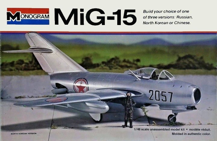
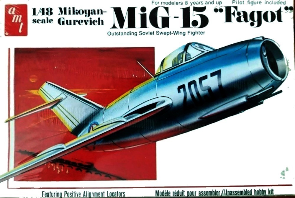
Thanks to Old Model Kits.com for use of this image.
Introduction
A few years ago, I was lucky to make the acquaintance of Mr. Robert Johnson III, who was with Monogram Models from 1973 into the 1990s. He started as a junior draftsman and worked his way into the planning and decision-making realm. You can read a fuller bio of him in the feature :
Creating a Model: Concept to Finished Model, Part 1
"Bob" has shared some fascinating stories of the hobby history, including how Lockheed's Kelly Johnson allowed Monogram into the Skunk Works to create the most accurate SR-71 of the era, what happened to Aurora molds and tooling, industry finances, and other "peaks behind the curtain." Some of those stories have been posted and all are amazing stories. The following is an insider's story about how Monogram achieved such accuracy with their kits since the 1970s.
Finding more accurate reference data...and the AMT MiG-15.
This article is similar to Model Industry History: Monogram's SR-71 and Their 5800-Series Aircraft Kits. The following recounts researching and designing Monogram's MiG-15 in Mr. Johnson's own words.
When I began working in the Engineering Department at Monogram Models, the endless “treasure trove” of data now found about vintage and new aircraft on the “worldwide web” was not even a glimmer in anyone’s eye. Locating reliable reference and dimensional data suitable for creating a new aircraft kit depended upon 3-view or 4-view drawings from a variety of sources. The Japanese aviation magazine “Koku-Fan” was a popular source, but, comparison to actual dimensional data often proved those drawings to be inaccurate. This began to change when data was gathered for the 1/48th scale Boeing B-17G. Alwyn Lloyd of Boeing supplied Roger Harney with a Pilot’s Manual that had good data, but, 30 years later, I came across a Technical Order dated 1943 titled “Familiarization and Inspection of the B-17F Airplane”...it was amazing!! I was able to provide a copy of a WWII manual titled “Gunner’s Information File” that had been used by my father in the 320th Bomb Group and detailed all gun turrets in B-17, B-24, B-25, B-26, and B-29aircraft. We also had a few pages from Tech Order 01-20EFS-1, B-17F Erection and Maintenance Manual. Nonetheless, accurate dimensional data had been hard to locate mostly because those seeking the data likely did not know what to look for.
While attending course 39BR4021, Aircraft Maintenance Officers’ Course, at Chanute AFB in 1971, we had a two week study block that enabled us to learn about specific Air Force Tech Orders that dealt with every aspect of a specific aircraft. For instance, a Tech Order titled “KC-135(K)A-1-1” was specifically for aircrew and contained all of the operational parameters for the KC-135A aircraft. The one that I found most interesting (and would become a superb source for future design work at Monogram) was “KC-135(K)A-2-1, Organizational (Flight Line) Maintenance Manual”. In the opening pages, the “General Aircraft” section provides detailed dimensional data for the external surfaces and geometric data that define all significant aircraft details. Specific drawings are provided (some to scale, some not) that provide plan view outlines of the fuselage, wing, horizontal stabilizer, and vertical stabilizer. Vertical planes are indicated that are known as “Stations” and each Station number indicates the distance in inches from a defined point; usually the frontplane of the nose.
The same concept provides data for Wing and Stabilizer Stations. Stations in the horizontal plane are defined as Waterlines. This type of data is available for every USAF military aircraft through Technical Orders and for USN aircraft through NATOPS manuals. In the 1970’s through 1990’s, this data could be obtained from Aircraft manufacturers, museums, and companies that dealt in aircraft parts and salvage. It was a revelation to me as a young Lt. and proved very helpful in the Engineering Department at Monogram Models to assist our design folks “understand” the shapes and size of aircraft. This type of data was totally new to the Monogram engineers, but, when it was used in concert with accurate three-view or four-view drawings obtained from aircraft manufacturers. John Brooks at McDonnell-Douglas St. Louis provided copies of1/10th scale wind tunnel models for the F-4C/D/J/E/F/S versions, F-15A/C/E, AV-8A, and FA-18A. The most difficult was obtaining data on Convair /Consolidated aircraft like the B-24 D/J, Convair F-102, F-106, and particularly the B-58 “Hustler”.
The data contained in these USAF / NATOPS manuals opened a new way of achieving dimensional accuracy in new Monogram projects, and it significantly increased the degree of accuracy that we were able to create.
The AMT / Monogram MiG-15 “Fracas”
One interesting project that began in 1975 involved the design and development of the North American F-86F (Kit 5402) and the Mikoyan Gurevich MiG-15 (Kit 5403). These two projects represented the beginning of post World War II subjects in 1/48th scale. The Tech Order data for the F-86 was fairly easy to obtain thanks to Vivian White from the USAFM Research Library. That data established the actual dimensions and geometry of the aircraft. While we did not have drawing data from Rockwell International, a “good” three-view from a secondary source and color reference photos taken at the USAF Museum made it fairly easy to use the T.O. data to create an accurate base drawing.
The MiG-15 proved to be a much larger challenge that began with acquiring basic overall dimensions for the length, wingspan, and height. Even this proved difficult as various books had differing data. The most accurate proved to be in Jane’s All the World’s Aircraft. But, in order to determine what the correct dimensions were, Mario Falconi and I traveled to the USAF Museum where Col. Uppstrom always welcomed us. Our goal was to photograph the F-86A with a the original wing and the MiG-15 that was delivered to South Korea by a North Korean pilot during the Korean War. We used a plumb bob and tape to mark the museum floor and take dimensions from those tape lines. The length and wingspan proved to be closest to a Polish aviation journal we had access to and measuring the actual North Korean MiG-15 obtained through “Project Moolah” revealed an interesting detail... the overall length of the aircraft was actually measured from the very front of the fuselage centerline to the very end of the fuselage not including the exhaust pipe, keeping in mind this aircraft (like many) does not sit level on the ground (the fuselage centerline not being parallel to the ground) I was glad Mario and I discovered this the “hard way”; by measuring an actual aircraft. The trailing edge of the vertical stabilizer overhangs the aft surface of the fuselage significantly. By discovering this, I believe it helped Mario interpret the dimensional data much better.
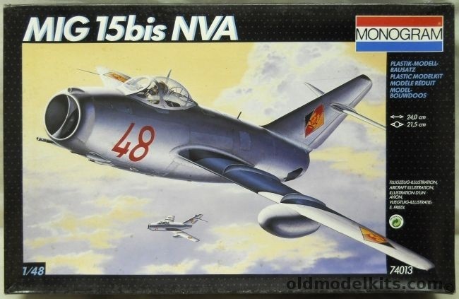
The two kits debuted in 1976. I felt each one “captured” the look and “sit” of the real aircraft. We had found two black and white photos of the North Korean pilot who defected with the aircraft on display at the Air Force Museum. Scotty Forte created a SUPERB” 4X clay sculpture of the pilot, it was fascinating “plus”! Some months later, Roger and I were called into Bob Reder’s office. It seemed that “the new Monogram President”, Tom Gannon, had received a letter from an former associate (of his) at AMT. The letter contained a new AMT model kit of their new 1/48th scale MiG-15 and claimed that “their’s was ‘right’" and Monogram’s had a fuselage that was too long. “Who was right?”, though it seemed more posed like “did you guys screw-up?” Time passes after a project is complete and I had forgotten the finding about the fuselage length. Discussing the parts with Mario, he suggested that we check the length of the fuselage against our measured dimensions. Mario’s fuselage was “spot on”... the AMT version was quite similar, but, that dimension was measured from the front surface of the nose air intake to the rear tip of the vertical stabilizer. The AMT engineers had likely used an available four-view that was scaled incorrectly.
We pointed out our findings to Roger, Reder, and Tom Gannon. Tom had one of those “gotcha” looks on his face. He asked that we mount down a Monogram fuselage half and an AMT fuselage half and note how long that part should be according to the actual overall fuselage length. Either Mario or I did as requested and passed it along to Roger.
Several years passed and Tom and I were either flying West to the Far East or East headed home from Japan and Taiwan. I asked him what became of the “MiG-15 situation” back in 1976?? He smiled and told me that he sent a letter to the fellow at AMT along with the mounted AMT and Monogram MiG-15, and a tooling quote from Ken Merker to tool two new fuselage halves. He told me it was all in good humor and the fellow at AMT saw it that was also. Sure glad that we had paid attention to “the small stuff”!!